

 Italiano
Shop
Showing 91–120 of 1498 results


-
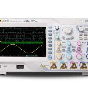
Oscilloscope 2 channels
Rigol MSO4032

350MHz, 2 channel, 4GS/s
MSO4000 Series is the new mainstream digital scope to meet the customer’s applications with its innovative technology, industry leading specifications, powerful trigger functions and broad analysis capabilities. – Bandwidth 350MHz – Sample Rate Analog channel up to 4 GSa/s, Digital Channel up to 1 GSa/s(MSO) – Standard Memory depth: Analog channel up to 140 Mpts, Digital Channel up to 28 Mpts(MSO) – 2 Analog Channels, 16 Digital channels(MSO) – Waveform capture rate Up to 110,000 waveforms per second, – Real Time Waveform Record, Replay & Analysis(Std. up to 200,000 frames) – Lower noise floor, the Min. vertical sensitivity is 1mV/div – Innovative “UltraVision” technology – A variety of Trigger functions – Support serial bus trigger(Std.) and decoding(Opt.) for both analog and digital channels – Complete Connectivity: USB Host& Device, LAN(LXI-C), VGA, AUX,USB-GPIB(Opt.) – 9 inch WVGA(800X480), 256 level intensity grading displaySKU: 729 -
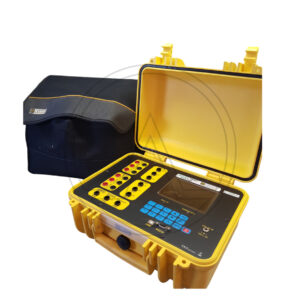
Green test
CHAUVIN ARNOUX GREEN FTV100

The Greentest FTV100 is a photovoltaic system verifier and certifier compliant with the CEI 82-25 Guide – Variant V1 for: Simultaneous display of all AC/DC measurements Calculation of panel efficiency Calculation of inverter efficiency Calculation of the PRp performance index Analysis of up to 3 panel strings simultaneously The GREENTEST FTV100 has a large 5.7″ color display. Easy to use and configure. Simply install the environmental measurement sensors: 1 Pt100 probe for measuring ambient temperature, a Pt100 probe for panel temperature and a pyranometer for irradiation. Connect the voltage cables and current clamps. Then enter the parameters dictated by the panel manufacturer. Finally, for the transmission of measurement results remotely, the instrument has a remote module (remote unit), which works with an RS232 cable (15 m) or with a Bluetooth system (up to 100 m – free field). The GreenReport software (included in the scope of delivery) allows the acquisition of all measurements in real time, the graphical analysis of all measurements and the printing of measurement results for certification through automatic report creation. Technical characteristics Voltage up to 1,000V DC / 600V AC Current up to 1,400A DC / 3,000A AC (depending on the clamp meter used) AC/DC power up to 5.4MW AC / 4.2MW DC (depending on the clamp meter used) Memory: up to 12 measurements for 10 different systems. System data can be entered via PC software Electrical safety EN 61010 600V Cat.IV and 1,000V Cat.III Degree of protection: IP67 (closed case) / IP54 (open case)
SKU: 1022 -
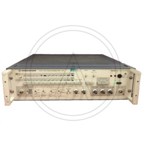
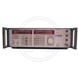
VIDEO TEST SIGNAL GENERATOR
ROHDE & SCHWARZ SPF2

The R&S SPF2 Video Test Signal Generator produces all the video signals for TV measurements in accordance with exisiing standards or with special waveforms and amplitudes and inserts these as test lines into the program signal.
The composite colour video signal (CCVS) for full-field measurements can have standard levels or the amplitudes of the individual signal components, such as sync pulse, picture component and composite (colour) video, can be adjusted.
The SPF2 combines a number of instrument functions: video signa l generator, test signal generator, noise generator, VTR test signal generator and test signal inserter.
* Standards B/G, D, H, I (PAL) and M (NTSC)
* Video signal generator
* Noise Generator
* VTR test signal generator
* Test signal generator
* Test signal inserterSKU: n/a -
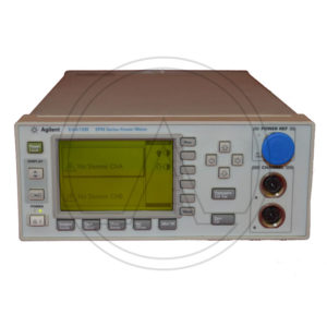
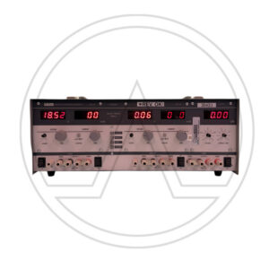
Power Meter
HP/Agilent-Keysight E4419B

The E4419B power meter is designed for bench and automatic test equipment (ATE) use.
True dual-channel power meter – two simultaneous power readings
Fast measurement speed (up to 100 readings per second, over the GPIB, with E-series sensors)
Speed improvement of x2 using the 8480 series power sensor (compared to the 437B)
No range-switching delays with 8480 series sensors, and only one fast-range switching point with E-series sensors
Code compatibility with 438A power meter
GPIB and RS232 connector for remote control of all functionsSupplemental characteristics (shown in italics) are intended to provide additional information, useful in applying the instrument by giving typical (expected), but not warranted performance parameters. These characteristics are shown in italics or labeled as “typical”, “nominal” or “approximate”.
For information on measurement uncertainty calculations, refer to Application Note 64-1C, “Fundamentals of RF and Microwave Power Measurements”, literature number 5965-6380E.
Frequency range: 9 kHz to 110 GHz, sensor dependent
Power range: –70 dBm to +44 dBm (100 pW to 25 W), sensor dependent.
Power sensors: Compatible with all 8480 series and E-series sensors
Single sensor dynamic range: 90 dB maximum (E-series sensors), 50 dB maximum ( 8480 series sensors).
Display units: Absolute: Watts or dBm. Relative: Percent or dB.
Display resolution: Selectable resolution of 1.0, 0.1, 0.01, and 0.001 dB in Log mode, or 1 to 4 digits in linear mode.
Default resolution: 0.01 dB in log mode, 3 digits in linear mode.
DatasheetSKU: n/a -
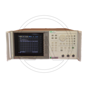
Network Analyzer
HP-Agilent/Keysight 8757D LCD

The HP 8757D LCD COLOR DISPLAY scalar network analyzer allows you to measure insertion loss, gain, return loss, SWR, and power quickly and accurately . With high-performance detectors and directional bridges, and a companion Keysight source and printer, this analyzer becomes the basis of a complete measurement system with superb performance.
Setup time is reduced by external disk save/recall, and measurement data can be sent directly to a printer while you proceed to the next measurement.
You can configure your system using a Keysight PSG signal generator with ramp sweep capability. The dynamic range can be extended from 75 dB to 83 dB using the PSG's high power option.
The Agilent 8757D has four independent display channels that process the signals from the Agilent 85037 series precision detectors, 85025 and 85026 detectors, and the 85027 series directional bridges for logarithmic display, in single channel or ratio mode. Three (optionally four) detector inputs are provided.
The number of points (horizontal resolution) that can be selected depends on the number of traces displayed.
A display is considered faulty if:
• A complete row or column of “stuck” or “dark” pixels.
• More than six “stuck on” pixels (but not more than three green) or more than 0.002% of the total pixels are within the LCD specifications.
• More than twelve “dark” pixels (but no more than seven of the same color) or more than 0.004% of the total pixels are within the LCD specifications.
• Two or more consecutive “stuck on” pixels or three or more consecutive “dark” pixel (but no more than one set of two consecutive dark pixels) “Stuck on” of “dark” pixels less than 6.5 mm apart (excluding consecutive pixels.All analyzer display channels can display any one of the detector inputs or any ratio combination of detector inputs.
Log magnitude >
dBm: single channel power measurement
dB: relative power measurement (ratio or relative to trace memory)SWR > Relative measurements (normalized or ratio measurements) can be displayed in SWR. Channels 1 and 2 only: 401 points or fewer
AUX voltage > The rear panel BNC input ADC IN can be measured and displayed in volts (–10 to +10 volts). Typical maximum error is 60 mV.
Up to 8 operator-selectable colors are available for LCD attributes, such as the grid, measurement traces, and labels.
The minimum sweep time depends on the number of traces displayed and the number of points selected.
Traces are stored and normalized with the highest resolution, independent of display scale/division or offset. With adaptive normalization on the Agilent 8757D, calibration data is interpolated when the frequency span is decreased.
Key Features & SpecificationsUp to 83 dB dynamic range
Buffered plotter/printer output
Built-in limit testing for quick pass/fail decisions
External disc and internal register save/recall of test setups
Color display
Optional internal power meter calibrator and precision detectors provide near power meter accuracy
DISLPAY CRT
Four display channels
Three detector inputs
+16 to –60 dBm dynamic range
AC/DC detection modes
101 to 1601 measurement points/trace
Compatible with the Agilent 85025 and 85026 series detectors and the Agilent 85027 series directional bridges
Limit line testing (channels 1 and 2)
Adaptive normalization
Cursor search functions (max, min, n dB, BW)SKU: 69-1 -
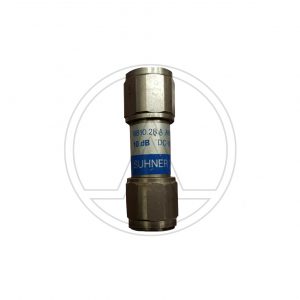
Cable
HUBER+SUHNER ENVIROFLEX 400,COAXIAL CABLE ,3m

HUBER+SUHNER ENVIROFLEX 400 COAXIAL CABLE – COLOR BLACK SMA M – SMA M 3m
The ENVIROFLEX 400 cable is suitable for a frequency range up to 6 GHz.
The RF line is flexible and recommended for wireless communication and HF applications.The Enviroflex cable family enables users to quickly switch from fluorine-containing cables to halogen-free alternatives. The materials used in the cable design – both for the dielectric and for the jacket – do not
include any fluorine-consisting plastics. The dimensions of the individual cable types are entirely compatible with the international RG standards. Standard connectors can be used without any restrictions with the Enviroflex cable family. HUBER+SUHNER´s control of various key technologies has proven to be an invaluable advantage.
DatasheetSKU: n/a -
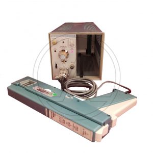
Current Probe Amplifiter, Mainframe
TEKTRONIX TM502A+AM503+A6303

Tektronix AM503 Current Probe Amplifier
The AM503 Current Probe Amplifier allows display of current on any oscilloscope having 10 mV/div sensitivity, 50 ohm or 1 megohm input, and at least 100 MHz bandwidth. It is compatible with A6302, A6303, P6302, P6303 current probes. It requires a TM500 or TM5000 series mainframe for operation.
Features:Allows for current display on any oscilloscope
Maximum input current: 20A for 6302; 100A for 6303
Bandwidth: >50 MHz 6302; >15 MHz 6303
Rise time: <7 ns 6302; <23 ns 6303
Deflection factor: 1 mA/div to 5 A/div for 6302; 20 mA/div to 50 A/div for 6303
Weight: 4 lb; Size: single width moduleSKU: n/a -
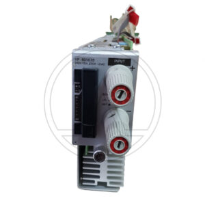
Power Supply
HP-Agilent/Keysight 6012B

These single-output supplies can replace multiple units, saving rack space and reducing system cost and complexity.
Autoranging outputs provide maximum power at a variety of operating points
Overvoltage features protect DUTs quickly and automatically
Auto-parallel or auto-series connections enable greater output flexibility
Ten-turn pots for precise local control1200W, DC System Power Supplies,60V – 50A.
DatasheetSKU: n/a -
Load
HP-Agilent/Keysight 60503B

The N3303A 250 Watt Electronic Load Module may not be used in a 6050A or 6051A Electronic Load Mainframe. The N3303A may only be used with a N3300A or N3301A Electronic Load Mainframe.
The Keysight 60503B module along with the dc electronic load mainframe are ideal for the test and evaluation of dc power sources and power components and are well suited for applications in areas such as research and development, production, and incoming inspection. Each module includes programming inputs that allow control of load current via an analog control voltage.
Analog voltage control in constant current mode
Full protection from over-current, over-voltage, overpower, over-temperature, and reverse polarity.SKU: n/a -
Signal Generator
ROHDE & SCHWARZ SMY01

Signal generators of the Rohde & Schwarz SMY family from Rohde&Schwarz are cost-effective instruments for testing AM, FM and jM receivers as well as for component measurements.
Designed exclusively for the main applications of signal generators by cutting out the unnecessaries, R&S SMY features an outstanding price/performance ratio. Thanks to its comprehensive basic features and excellent signal characteristics, it is an economical solution for universal use in lab, production and servicing environments.
Level range -140 dBm to +13 dBm (19 dBm overrange) , sufficient even for receivers of highest sensitivity
High level accuracy and low RF leakage allowing accurate and undegraded sensitivity measurements
FM-DC with high accuracy of carrier frequency for testing pagers and receivers fitted with digital squelches
Low SSB phase noise( -114 dBc/Hz) and high spurious rejection for all in-channel and blocking measurements
Low residual FM affording ample of margin for S/N measurements
Modulation generator 1 Hz to 500 kHz for modulation frequency response measurements
Stereo channel separation of 50 dB and low harmonic distortion for testing FM stereo receivers
Non-interrupting level setting over a range of 20 dB for reproducible measurement of squelch hysteresis
Frequency resolution 1 Hz, suitable also for narrowband test items
FM-DC, deviation up to 20 MHz for VCO simulation
FM bandwidth 2 MHz for fast FSK and telemetry applications
High output level up to 19 dBm (25 dBm with option R&S SMY-B40) for component and overdrive testing
AF synthesizer 1 Hz to 500 kHz, separate use as AF signal source for external applications possible, eg recording of AF frequency response
Remote-control interface IEC625/IEEE488 for use in automatic test systems
RF sweep
Sequence function and SEQ input for semi-automatic useSKU: n/a -
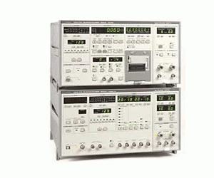
Trasmitter/Receiver
Anritsu ME522A

The Anritsu ME522A PCM Measuring Instrument/ Error Rate Measuring Set consits of receiver and transmitter unit. It covers the 1 to 700 MHz frequency range, up to 1,4 GHz using a plugin. – Built-in synthesizer – Abundant measuring patterns – Flexible input/output interface. Level, waveform, and impedance can be set according to the system – Powerful error measuring functions – HP-IB control – Receiver The receiver comes with MH677A demultiplexer. Operating frequency reaches from 700 MHz to 1,4 GHz (input) and 350 to 700 MHz (output). – Built-in recorder. – Transmitter The transmitter comes with U/B converter MH5104A which provides a 564,992 ± 6 MHz operating frequency.
1 to 700 MHz.SKU: 3
-
Oscilloscope 2 channels
Rigol MSO4032
350MHz, 2 channel, 4GS/s
MSO4000 Series is the new mainstream digital scope to meet the customer’s applications with its innovative technology, industry leading specifications, powerful trigger functions and broad analysis capabilities. – Bandwidth 350MHz – Sample Rate Analog channel up to 4 GSa/s, Digital Channel up to 1 GSa/s(MSO) – Standard Memory depth: Analog channel up to 140 Mpts, Digital Channel up to 28 Mpts(MSO) – 2 Analog Channels, 16 Digital channels(MSO) – Waveform capture rate Up to 110,000 waveforms per second, – Real Time Waveform Record, Replay & Analysis(Std. up to 200,000 frames) – Lower noise floor, the Min. vertical sensitivity is 1mV/div – Innovative “UltraVision” technology – A variety of Trigger functions – Support serial bus trigger(Std.) and decoding(Opt.) for both analog and digital channels – Complete Connectivity: USB Host& Device, LAN(LXI-C), VGA, AUX,USB-GPIB(Opt.) – 9 inch WVGA(800X480), 256 level intensity grading display -
Green test
CHAUVIN ARNOUX GREEN FTV100
The Greentest FTV100 is a photovoltaic system verifier and certifier compliant with the CEI 82-25 Guide – Variant V1 for: Simultaneous display of all AC/DC measurements Calculation of panel efficiency Calculation of inverter efficiency Calculation of the PRp performance index Analysis of up to 3 panel strings simultaneously The GREENTEST FTV100 has a large 5.7″ color display. Easy to use and configure. Simply install the environmental measurement sensors: 1 Pt100 probe for measuring ambient temperature, a Pt100 probe for panel temperature and a pyranometer for irradiation. Connect the voltage cables and current clamps. Then enter the parameters dictated by the panel manufacturer. Finally, for the transmission of measurement results remotely, the instrument has a remote module (remote unit), which works with an RS232 cable (15 m) or with a Bluetooth system (up to 100 m – free field). The GreenReport software (included in the scope of delivery) allows the acquisition of all measurements in real time, the graphical analysis of all measurements and the printing of measurement results for certification through automatic report creation. Technical characteristics Voltage up to 1,000V DC / 600V AC Current up to 1,400A DC / 3,000A AC (depending on the clamp meter used) AC/DC power up to 5.4MW AC / 4.2MW DC (depending on the clamp meter used) Memory: up to 12 measurements for 10 different systems. System data can be entered via PC software Electrical safety EN 61010 600V Cat.IV and 1,000V Cat.III Degree of protection: IP67 (closed case) / IP54 (open case)
-
VIDEO TEST SIGNAL GENERATOR
ROHDE & SCHWARZ SPF2
The R&S SPF2 Video Test Signal Generator produces all the video signals for TV measurements in accordance with exisiing standards or with special waveforms and amplitudes and inserts these as test lines into the program signal.
The composite colour video signal (CCVS) for full-field measurements can have standard levels or the amplitudes of the individual signal components, such as sync pulse, picture component and composite (colour) video, can be adjusted.
The SPF2 combines a number of instrument functions: video signa l generator, test signal generator, noise generator, VTR test signal generator and test signal inserter.
* Standards B/G, D, H, I (PAL) and M (NTSC)
* Video signal generator
* Noise Generator
* VTR test signal generator
* Test signal generator
* Test signal inserter -
Power Meter
HP/Agilent-Keysight E4419B
The E4419B power meter is designed for bench and automatic test equipment (ATE) use.
True dual-channel power meter – two simultaneous power readings
Fast measurement speed (up to 100 readings per second, over the GPIB, with E-series sensors)
Speed improvement of x2 using the 8480 series power sensor (compared to the 437B)
No range-switching delays with 8480 series sensors, and only one fast-range switching point with E-series sensors
Code compatibility with 438A power meter
GPIB and RS232 connector for remote control of all functionsSupplemental characteristics (shown in italics) are intended to provide additional information, useful in applying the instrument by giving typical (expected), but not warranted performance parameters. These characteristics are shown in italics or labeled as “typical”, “nominal” or “approximate”.
For information on measurement uncertainty calculations, refer to Application Note 64-1C, “Fundamentals of RF and Microwave Power Measurements”, literature number 5965-6380E.
Frequency range: 9 kHz to 110 GHz, sensor dependent
Power range: –70 dBm to +44 dBm (100 pW to 25 W), sensor dependent.
Power sensors: Compatible with all 8480 series and E-series sensors
Single sensor dynamic range: 90 dB maximum (E-series sensors), 50 dB maximum ( 8480 series sensors).
Display units: Absolute: Watts or dBm. Relative: Percent or dB.
Display resolution: Selectable resolution of 1.0, 0.1, 0.01, and 0.001 dB in Log mode, or 1 to 4 digits in linear mode.
Default resolution: 0.01 dB in log mode, 3 digits in linear mode.
Datasheet -
Network Analyzer
HP-Agilent/Keysight 8757D LCD
The HP 8757D LCD COLOR DISPLAY scalar network analyzer allows you to measure insertion loss, gain, return loss, SWR, and power quickly and accurately . With high-performance detectors and directional bridges, and a companion Keysight source and printer, this analyzer becomes the basis of a complete measurement system with superb performance.
Setup time is reduced by external disk save/recall, and measurement data can be sent directly to a printer while you proceed to the next measurement.
You can configure your system using a Keysight PSG signal generator with ramp sweep capability. The dynamic range can be extended from 75 dB to 83 dB using the PSG's high power option.
The Agilent 8757D has four independent display channels that process the signals from the Agilent 85037 series precision detectors, 85025 and 85026 detectors, and the 85027 series directional bridges for logarithmic display, in single channel or ratio mode. Three (optionally four) detector inputs are provided.
The number of points (horizontal resolution) that can be selected depends on the number of traces displayed.
A display is considered faulty if:
• A complete row or column of “stuck” or “dark” pixels.
• More than six “stuck on” pixels (but not more than three green) or more than 0.002% of the total pixels are within the LCD specifications.
• More than twelve “dark” pixels (but no more than seven of the same color) or more than 0.004% of the total pixels are within the LCD specifications.
• Two or more consecutive “stuck on” pixels or three or more consecutive “dark” pixel (but no more than one set of two consecutive dark pixels) “Stuck on” of “dark” pixels less than 6.5 mm apart (excluding consecutive pixels.All analyzer display channels can display any one of the detector inputs or any ratio combination of detector inputs.
Log magnitude >
dBm: single channel power measurement
dB: relative power measurement (ratio or relative to trace memory)SWR > Relative measurements (normalized or ratio measurements) can be displayed in SWR. Channels 1 and 2 only: 401 points or fewer
AUX voltage > The rear panel BNC input ADC IN can be measured and displayed in volts (–10 to +10 volts). Typical maximum error is 60 mV.
Up to 8 operator-selectable colors are available for LCD attributes, such as the grid, measurement traces, and labels.
The minimum sweep time depends on the number of traces displayed and the number of points selected.
Traces are stored and normalized with the highest resolution, independent of display scale/division or offset. With adaptive normalization on the Agilent 8757D, calibration data is interpolated when the frequency span is decreased.
Key Features & SpecificationsUp to 83 dB dynamic range
Buffered plotter/printer output
Built-in limit testing for quick pass/fail decisions
External disc and internal register save/recall of test setups
Color display
Optional internal power meter calibrator and precision detectors provide near power meter accuracy
DISLPAY CRT
Four display channels
Three detector inputs
+16 to –60 dBm dynamic range
AC/DC detection modes
101 to 1601 measurement points/trace
Compatible with the Agilent 85025 and 85026 series detectors and the Agilent 85027 series directional bridges
Limit line testing (channels 1 and 2)
Adaptive normalization
Cursor search functions (max, min, n dB, BW) -
Cable
HUBER+SUHNER ENVIROFLEX 400,COAXIAL CABLE ,3m
HUBER+SUHNER ENVIROFLEX 400 COAXIAL CABLE – COLOR BLACK SMA M – SMA M 3m
The ENVIROFLEX 400 cable is suitable for a frequency range up to 6 GHz.
The RF line is flexible and recommended for wireless communication and HF applications.The Enviroflex cable family enables users to quickly switch from fluorine-containing cables to halogen-free alternatives. The materials used in the cable design – both for the dielectric and for the jacket – do not
include any fluorine-consisting plastics. The dimensions of the individual cable types are entirely compatible with the international RG standards. Standard connectors can be used without any restrictions with the Enviroflex cable family. HUBER+SUHNER´s control of various key technologies has proven to be an invaluable advantage.
Datasheet -
Current Probe Amplifiter, Mainframe
TEKTRONIX TM502A+AM503+A6303
Tektronix AM503 Current Probe Amplifier
The AM503 Current Probe Amplifier allows display of current on any oscilloscope having 10 mV/div sensitivity, 50 ohm or 1 megohm input, and at least 100 MHz bandwidth. It is compatible with A6302, A6303, P6302, P6303 current probes. It requires a TM500 or TM5000 series mainframe for operation.
Features:Allows for current display on any oscilloscope
Maximum input current: 20A for 6302; 100A for 6303
Bandwidth: >50 MHz 6302; >15 MHz 6303
Rise time: <7 ns 6302; <23 ns 6303
Deflection factor: 1 mA/div to 5 A/div for 6302; 20 mA/div to 50 A/div for 6303
Weight: 4 lb; Size: single width module -
Power Supply
HP-Agilent/Keysight 6012B
These single-output supplies can replace multiple units, saving rack space and reducing system cost and complexity.
Autoranging outputs provide maximum power at a variety of operating points
Overvoltage features protect DUTs quickly and automatically
Auto-parallel or auto-series connections enable greater output flexibility
Ten-turn pots for precise local control1200W, DC System Power Supplies,60V – 50A.
Datasheet -
Load
HP-Agilent/Keysight 60503B
The N3303A 250 Watt Electronic Load Module may not be used in a 6050A or 6051A Electronic Load Mainframe. The N3303A may only be used with a N3300A or N3301A Electronic Load Mainframe.
The Keysight 60503B module along with the dc electronic load mainframe are ideal for the test and evaluation of dc power sources and power components and are well suited for applications in areas such as research and development, production, and incoming inspection. Each module includes programming inputs that allow control of load current via an analog control voltage.
Analog voltage control in constant current mode
Full protection from over-current, over-voltage, overpower, over-temperature, and reverse polarity. -
Signal Generator
ROHDE & SCHWARZ SMY01
Signal generators of the Rohde & Schwarz SMY family from Rohde&Schwarz are cost-effective instruments for testing AM, FM and jM receivers as well as for component measurements.
Designed exclusively for the main applications of signal generators by cutting out the unnecessaries, R&S SMY features an outstanding price/performance ratio. Thanks to its comprehensive basic features and excellent signal characteristics, it is an economical solution for universal use in lab, production and servicing environments.
Level range -140 dBm to +13 dBm (19 dBm overrange) , sufficient even for receivers of highest sensitivity
High level accuracy and low RF leakage allowing accurate and undegraded sensitivity measurements
FM-DC with high accuracy of carrier frequency for testing pagers and receivers fitted with digital squelches
Low SSB phase noise( -114 dBc/Hz) and high spurious rejection for all in-channel and blocking measurements
Low residual FM affording ample of margin for S/N measurements
Modulation generator 1 Hz to 500 kHz for modulation frequency response measurements
Stereo channel separation of 50 dB and low harmonic distortion for testing FM stereo receivers
Non-interrupting level setting over a range of 20 dB for reproducible measurement of squelch hysteresis
Frequency resolution 1 Hz, suitable also for narrowband test items
FM-DC, deviation up to 20 MHz for VCO simulation
FM bandwidth 2 MHz for fast FSK and telemetry applications
High output level up to 19 dBm (25 dBm with option R&S SMY-B40) for component and overdrive testing
AF synthesizer 1 Hz to 500 kHz, separate use as AF signal source for external applications possible, eg recording of AF frequency response
Remote-control interface IEC625/IEEE488 for use in automatic test systems
RF sweep
Sequence function and SEQ input for semi-automatic use -
Trasmitter/Receiver
Anritsu ME522A
The Anritsu ME522A PCM Measuring Instrument/ Error Rate Measuring Set consits of receiver and transmitter unit. It covers the 1 to 700 MHz frequency range, up to 1,4 GHz using a plugin. – Built-in synthesizer – Abundant measuring patterns – Flexible input/output interface. Level, waveform, and impedance can be set according to the system – Powerful error measuring functions – HP-IB control – Receiver The receiver comes with MH677A demultiplexer. Operating frequency reaches from 700 MHz to 1,4 GHz (input) and 350 to 700 MHz (output). – Built-in recorder. – Transmitter The transmitter comes with U/B converter MH5104A which provides a 564,992 ± 6 MHz operating frequency.
1 to 700 MHz.
-
Oscilloscope 2 channels
Rigol MSO4032
350MHz, 2 channel, 4GS/s
MSO4000 Series is the new mainstream digital scope to meet the customer’s applications with its innovative technology, industry leading specifications, powerful trigger functions and broad analysis capabilities. – Bandwidth 350MHz – Sample Rate Analog channel up to 4 GSa/s, Digital Channel up to 1 GSa/s(MSO) – Standard Memory depth: Analog channel up to 140 Mpts, Digital Channel up to 28 Mpts(MSO) – 2 Analog Channels, 16 Digital channels(MSO) – Waveform capture rate Up to 110,000 waveforms per second, – Real Time Waveform Record, Replay & Analysis(Std. up to 200,000 frames) – Lower noise floor, the Min. vertical sensitivity is 1mV/div – Innovative “UltraVision” technology – A variety of Trigger functions – Support serial bus trigger(Std.) and decoding(Opt.) for both analog and digital channels – Complete Connectivity: USB Host& Device, LAN(LXI-C), VGA, AUX,USB-GPIB(Opt.) – 9 inch WVGA(800X480), 256 level intensity grading display -
Green test
CHAUVIN ARNOUX GREEN FTV100
The Greentest FTV100 is a photovoltaic system verifier and certifier compliant with the CEI 82-25 Guide – Variant V1 for: Simultaneous display of all AC/DC measurements Calculation of panel efficiency Calculation of inverter efficiency Calculation of the PRp performance index Analysis of up to 3 panel strings simultaneously The GREENTEST FTV100 has a large 5.7″ color display. Easy to use and configure. Simply install the environmental measurement sensors: 1 Pt100 probe for measuring ambient temperature, a Pt100 probe for panel temperature and a pyranometer for irradiation. Connect the voltage cables and current clamps. Then enter the parameters dictated by the panel manufacturer. Finally, for the transmission of measurement results remotely, the instrument has a remote module (remote unit), which works with an RS232 cable (15 m) or with a Bluetooth system (up to 100 m – free field). The GreenReport software (included in the scope of delivery) allows the acquisition of all measurements in real time, the graphical analysis of all measurements and the printing of measurement results for certification through automatic report creation. Technical characteristics Voltage up to 1,000V DC / 600V AC Current up to 1,400A DC / 3,000A AC (depending on the clamp meter used) AC/DC power up to 5.4MW AC / 4.2MW DC (depending on the clamp meter used) Memory: up to 12 measurements for 10 different systems. System data can be entered via PC software Electrical safety EN 61010 600V Cat.IV and 1,000V Cat.III Degree of protection: IP67 (closed case) / IP54 (open case)
-
VIDEO TEST SIGNAL GENERATOR
ROHDE & SCHWARZ SPF2
The R&S SPF2 Video Test Signal Generator produces all the video signals for TV measurements in accordance with exisiing standards or with special waveforms and amplitudes and inserts these as test lines into the program signal.
The composite colour video signal (CCVS) for full-field measurements can have standard levels or the amplitudes of the individual signal components, such as sync pulse, picture component and composite (colour) video, can be adjusted.
The SPF2 combines a number of instrument functions: video signa l generator, test signal generator, noise generator, VTR test signal generator and test signal inserter.
* Standards B/G, D, H, I (PAL) and M (NTSC)
* Video signal generator
* Noise Generator
* VTR test signal generator
* Test signal generator
* Test signal inserter -
Power Meter
HP/Agilent-Keysight E4419B
The E4419B power meter is designed for bench and automatic test equipment (ATE) use.
True dual-channel power meter – two simultaneous power readings
Fast measurement speed (up to 100 readings per second, over the GPIB, with E-series sensors)
Speed improvement of x2 using the 8480 series power sensor (compared to the 437B)
No range-switching delays with 8480 series sensors, and only one fast-range switching point with E-series sensors
Code compatibility with 438A power meter
GPIB and RS232 connector for remote control of all functionsSupplemental characteristics (shown in italics) are intended to provide additional information, useful in applying the instrument by giving typical (expected), but not warranted performance parameters. These characteristics are shown in italics or labeled as “typical”, “nominal” or “approximate”.
For information on measurement uncertainty calculations, refer to Application Note 64-1C, “Fundamentals of RF and Microwave Power Measurements”, literature number 5965-6380E.
Frequency range: 9 kHz to 110 GHz, sensor dependent
Power range: –70 dBm to +44 dBm (100 pW to 25 W), sensor dependent.
Power sensors: Compatible with all 8480 series and E-series sensors
Single sensor dynamic range: 90 dB maximum (E-series sensors), 50 dB maximum ( 8480 series sensors).
Display units: Absolute: Watts or dBm. Relative: Percent or dB.
Display resolution: Selectable resolution of 1.0, 0.1, 0.01, and 0.001 dB in Log mode, or 1 to 4 digits in linear mode.
Default resolution: 0.01 dB in log mode, 3 digits in linear mode.
Datasheet -
Network Analyzer
HP-Agilent/Keysight 8757D LCD
The HP 8757D LCD COLOR DISPLAY scalar network analyzer allows you to measure insertion loss, gain, return loss, SWR, and power quickly and accurately . With high-performance detectors and directional bridges, and a companion Keysight source and printer, this analyzer becomes the basis of a complete measurement system with superb performance.
Setup time is reduced by external disk save/recall, and measurement data can be sent directly to a printer while you proceed to the next measurement.
You can configure your system using a Keysight PSG signal generator with ramp sweep capability. The dynamic range can be extended from 75 dB to 83 dB using the PSG's high power option.
The Agilent 8757D has four independent display channels that process the signals from the Agilent 85037 series precision detectors, 85025 and 85026 detectors, and the 85027 series directional bridges for logarithmic display, in single channel or ratio mode. Three (optionally four) detector inputs are provided.
The number of points (horizontal resolution) that can be selected depends on the number of traces displayed.
A display is considered faulty if:
• A complete row or column of “stuck” or “dark” pixels.
• More than six “stuck on” pixels (but not more than three green) or more than 0.002% of the total pixels are within the LCD specifications.
• More than twelve “dark” pixels (but no more than seven of the same color) or more than 0.004% of the total pixels are within the LCD specifications.
• Two or more consecutive “stuck on” pixels or three or more consecutive “dark” pixel (but no more than one set of two consecutive dark pixels) “Stuck on” of “dark” pixels less than 6.5 mm apart (excluding consecutive pixels.All analyzer display channels can display any one of the detector inputs or any ratio combination of detector inputs.
Log magnitude >
dBm: single channel power measurement
dB: relative power measurement (ratio or relative to trace memory)SWR > Relative measurements (normalized or ratio measurements) can be displayed in SWR. Channels 1 and 2 only: 401 points or fewer
AUX voltage > The rear panel BNC input ADC IN can be measured and displayed in volts (–10 to +10 volts). Typical maximum error is 60 mV.
Up to 8 operator-selectable colors are available for LCD attributes, such as the grid, measurement traces, and labels.
The minimum sweep time depends on the number of traces displayed and the number of points selected.
Traces are stored and normalized with the highest resolution, independent of display scale/division or offset. With adaptive normalization on the Agilent 8757D, calibration data is interpolated when the frequency span is decreased.
Key Features & SpecificationsUp to 83 dB dynamic range
Buffered plotter/printer output
Built-in limit testing for quick pass/fail decisions
External disc and internal register save/recall of test setups
Color display
Optional internal power meter calibrator and precision detectors provide near power meter accuracy
DISLPAY CRT
Four display channels
Three detector inputs
+16 to –60 dBm dynamic range
AC/DC detection modes
101 to 1601 measurement points/trace
Compatible with the Agilent 85025 and 85026 series detectors and the Agilent 85027 series directional bridges
Limit line testing (channels 1 and 2)
Adaptive normalization
Cursor search functions (max, min, n dB, BW) -
Cable
HUBER+SUHNER ENVIROFLEX 400,COAXIAL CABLE ,3m
HUBER+SUHNER ENVIROFLEX 400 COAXIAL CABLE – COLOR BLACK SMA M – SMA M 3m
The ENVIROFLEX 400 cable is suitable for a frequency range up to 6 GHz.
The RF line is flexible and recommended for wireless communication and HF applications.The Enviroflex cable family enables users to quickly switch from fluorine-containing cables to halogen-free alternatives. The materials used in the cable design – both for the dielectric and for the jacket – do not
include any fluorine-consisting plastics. The dimensions of the individual cable types are entirely compatible with the international RG standards. Standard connectors can be used without any restrictions with the Enviroflex cable family. HUBER+SUHNER´s control of various key technologies has proven to be an invaluable advantage.
Datasheet -
Current Probe Amplifiter, Mainframe
TEKTRONIX TM502A+AM503+A6303
Tektronix AM503 Current Probe Amplifier
The AM503 Current Probe Amplifier allows display of current on any oscilloscope having 10 mV/div sensitivity, 50 ohm or 1 megohm input, and at least 100 MHz bandwidth. It is compatible with A6302, A6303, P6302, P6303 current probes. It requires a TM500 or TM5000 series mainframe for operation.
Features:Allows for current display on any oscilloscope
Maximum input current: 20A for 6302; 100A for 6303
Bandwidth: >50 MHz 6302; >15 MHz 6303
Rise time: <7 ns 6302; <23 ns 6303
Deflection factor: 1 mA/div to 5 A/div for 6302; 20 mA/div to 50 A/div for 6303
Weight: 4 lb; Size: single width module -
Power Supply
HP-Agilent/Keysight 6012B
These single-output supplies can replace multiple units, saving rack space and reducing system cost and complexity.
Autoranging outputs provide maximum power at a variety of operating points
Overvoltage features protect DUTs quickly and automatically
Auto-parallel or auto-series connections enable greater output flexibility
Ten-turn pots for precise local control1200W, DC System Power Supplies,60V – 50A.
Datasheet -
Load
HP-Agilent/Keysight 60503B
The N3303A 250 Watt Electronic Load Module may not be used in a 6050A or 6051A Electronic Load Mainframe. The N3303A may only be used with a N3300A or N3301A Electronic Load Mainframe.
The Keysight 60503B module along with the dc electronic load mainframe are ideal for the test and evaluation of dc power sources and power components and are well suited for applications in areas such as research and development, production, and incoming inspection. Each module includes programming inputs that allow control of load current via an analog control voltage.
Analog voltage control in constant current mode
Full protection from over-current, over-voltage, overpower, over-temperature, and reverse polarity. -
Signal Generator
ROHDE & SCHWARZ SMY01
Signal generators of the Rohde & Schwarz SMY family from Rohde&Schwarz are cost-effective instruments for testing AM, FM and jM receivers as well as for component measurements.
Designed exclusively for the main applications of signal generators by cutting out the unnecessaries, R&S SMY features an outstanding price/performance ratio. Thanks to its comprehensive basic features and excellent signal characteristics, it is an economical solution for universal use in lab, production and servicing environments.
Level range -140 dBm to +13 dBm (19 dBm overrange) , sufficient even for receivers of highest sensitivity
High level accuracy and low RF leakage allowing accurate and undegraded sensitivity measurements
FM-DC with high accuracy of carrier frequency for testing pagers and receivers fitted with digital squelches
Low SSB phase noise( -114 dBc/Hz) and high spurious rejection for all in-channel and blocking measurements
Low residual FM affording ample of margin for S/N measurements
Modulation generator 1 Hz to 500 kHz for modulation frequency response measurements
Stereo channel separation of 50 dB and low harmonic distortion for testing FM stereo receivers
Non-interrupting level setting over a range of 20 dB for reproducible measurement of squelch hysteresis
Frequency resolution 1 Hz, suitable also for narrowband test items
FM-DC, deviation up to 20 MHz for VCO simulation
FM bandwidth 2 MHz for fast FSK and telemetry applications
High output level up to 19 dBm (25 dBm with option R&S SMY-B40) for component and overdrive testing
AF synthesizer 1 Hz to 500 kHz, separate use as AF signal source for external applications possible, eg recording of AF frequency response
Remote-control interface IEC625/IEEE488 for use in automatic test systems
RF sweep
Sequence function and SEQ input for semi-automatic use -
Trasmitter/Receiver
Anritsu ME522A
The Anritsu ME522A PCM Measuring Instrument/ Error Rate Measuring Set consits of receiver and transmitter unit. It covers the 1 to 700 MHz frequency range, up to 1,4 GHz using a plugin. – Built-in synthesizer – Abundant measuring patterns – Flexible input/output interface. Level, waveform, and impedance can be set according to the system – Powerful error measuring functions – HP-IB control – Receiver The receiver comes with MH677A demultiplexer. Operating frequency reaches from 700 MHz to 1,4 GHz (input) and 350 to 700 MHz (output). – Built-in recorder. – Transmitter The transmitter comes with U/B converter MH5104A which provides a 564,992 ± 6 MHz operating frequency.
1 to 700 MHz.